Search
aerospace

Vertiport Assessment and Mobility Operations System (VAMOS!)
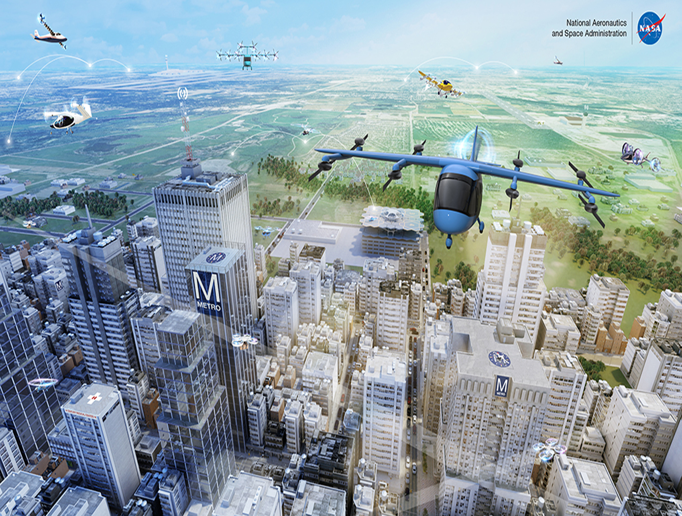
The term Advanced Air Mobility (AAM) refers to a new mode of transportation utilizing highly automated airborne vehicles for transporting goods and/or people. The adoption of widespread use of AAM vehicles will necessitate a network of vertiports located throughout a geographical region. A vertiport refers to a physical structure for the departure, arrival, and parking/storage of AAM vehicles. NASA-developed Vertiport Assessment and Mobility Operations System (VAMOS!) enables identifying geographical locations suitable for locating a vertiport or assessing suitability of pre-selected locations. For example, suitability evaluation factors include zoning, land use, transit stations, fire stations, noise, and time-varying factors like congestion and demand.
The vertiport assessment system assigns suitability values to these factors based on user-input, and types, including location-based (e.g., proximity to mass transit stations), level-based (e.g., noise levels), characteristic-based (e.g., residential zoning), and time-based (e.g., demand). Based on user input, the system spreads a grid over the geographical area, specifies importance criteria and weights for scaling the impact of the suitability factors, and identifies specific sub-regions as candidate locations. The candidate sub-regions are shown on a user interface map overlay in a color-coded gradient that reflects the suitability strength for a sub-region. Vertiport locations are selected within these sub-regions. These candidate vertiport locations are refined by establishing feasibility of flight between them. VAMOS! includes a modeling component and a simulation component. The modeling component assists a user to identify one or more geographical locations at which a vertiport may be physically built. The simulation component of the technology displays, in real-time, the simulated operational behavior of AAM vehicles and in the context of their projected flight paths combined with data dynamically obtained from live sources. These data sources can be from the Federal Aviation Administration (FAA) or other private or public governing bodies, from one or more AAM vehicles in flight, and from weather sources.
Aerospace

Aerodynamic Framework for Parachute Deployment from Aerial Vehicle
For rapid parachute deployment simulation, the framework and methodology provided by the simulation database uses parametrized aerodynamic data for a variety of environmental conditions, air taxi design parameters, and landing system designs. The database also includes a compilation of drag coefficients, thrust and lift forces, and further relevant aerodynamic parameters utilized in the simulated flight of a proposed air taxi. The database and framework can be constructed using simulated data that accounts for oscillatory breathing of parachutes. The methodology can further employ an overset grid of body-fitted meshes to accurately capture deployment of an internally-stored parachute, as well as descent of the air taxi and deployed parachute.
The systems and methods of the disclosed technology can be utilized with existing CFD solvers in a plug-and-play manner, such that the framework can be integrated to directly improve the performance of these solvers and the machines on which they are installed. The framework itself can employ parallelization to enable distributed solution of intensive CFD simulations to build a robust database of simulated data. Further, as up to 90% of computational time is spent in the calculation of aerodynamic parameters for use in coupled trajectory equations, the framework can significantly reduce the computational costs and design time for safe landing systems for air taxis. These reductions can lead to lower costs for design processes, while enabling rapid design and testing prior to physical prototyping.
Mechanical and Fluid Systems
Active Flow Control System for Simple-hinged Flaps
Although simple-hinged flaps represent optimal high-lift systems for reducing cruise drag, previous attempts to design flow control systems enabling such technology in transport aircraft have been unsuccessful. This is largely because such systems generally require a tradeoff between (a) the ability to achieve the required lift performance, and (b) possessing sufficiently low pneumatic power to enable feasible aircraft system integration (i.e., avoiding excess weight penalties associated with high pneumatic power). For example, electrically powered AFC systems (e.g., plasma actuators, synthetic jet actuators) have practical power requirements, but with limited control authority, making such systems ineffective for highly deflected flaps. On the other hand, circulation control systems can provide necessary lift for airfoils or wings with high flap deflections, but require too much pneumatic power for aircraft integration. NASA’s HELP AFC system represents a breakthrough in flow separation control technology – to efficiently achieve necessary lift performances while requiring low pneumatic power relative to alternative flow control techniques.
NASA’s HELP AFC system uses a unique two-row actuator approach comprised of upstream sweeping jet (SWJ) actuators and downstream discrete jets, which share the same air supply plenum. The upstream (row 1) SWJ actuators provide good spanwise flow-control coverage with relatively mass flow, effectively pre-conditioning the boundary layer such that the downstream (row 2) discrete jets achieve better flow control authority. The two row actuator system, working together, produce a total aerodynamic lift greater than the sum of each row acting individually. The result is a system that generates sufficient lift performance for simple-hinged flaps with pneumatic power requirements low enough to enable aircraft integration.
Aerospace

Vision-based Approach and Landing System (VALS)
The novel Vision-based Approach and Landing System (VALS) provides Advanced Air Mobility (AAM) aircraft with an Alternative Position, Navigation, and Timing (APNT) solution for approach and landing without relying on GPS. VALS operates on multiple images obtained by the aircraft’s video camera as the aircraft performs its descent. In this system, a feature detection technique such as Hough circles and Harris corner detection is used to detect which portions of the image may have landmark features. These image areas are compared with a stored list of known landmarks to determine which features correspond to the known landmarks. The world coordinates of the best matched image landmarks are inputted into a Coplanar Pose from Orthography and Scaling with Iterations (COPOSIT) module to estimate the camera position relative to the landmark points, which yields an estimate of the position and orientation of the aircraft. The estimated aircraft position and orientation are fed into an extended Kalman filter to further refine the estimation of aircraft position, velocity, and orientation. Thus, the aircraft’s position, velocity, and orientation are determined without the use of GPS data or signals. Future work includes feeding the vision-based navigation data into the aircraft’s flight control system to facilitate aircraft landing.
Aerospace
Wind-Optimal Cruise Airspeed Mode for Flight Management Systems (FMS)
The novel approach for optimizing airspeed for both actual and predicted wind conditions in electric Vertical Takeoff and Landing (eVTOL) aircraft with Distributed Electric Propulsion (DEP) systems includes the process of creating a lookup table for wind‐optimal airspeed as a function of wind magnitude, considering the direction of the wind relative to the cruise segment, considering the cruise altitude for an aircraft type, and incorporating the wind-optimal airspeed lookup table in the performance database for real‐time access by the Flight Management Systems (FMS) to predict wind-optimal airspeed at waypoints of the flight plan. The target wind‐optimal airspeed is updated in real-time throughout the cruise portion of a flight.
In a test of the wind-optimal airspeed targeting technique using a multi-rotor aircraft model, results obtained show benefits of flying at the wind‐optimal cruise airspeed compared to the best‐range airspeed. In headwind conditions, energy consumption was reduced by up to 7.5%, and flight duration was reduced by up to 28%. Under uncertain wind magnitudes, flying at wind-optimal airspeed offered lower variability and higher predictability in energy consumption than flying at best‐range airspeed.
Mechanical and Fluid Systems
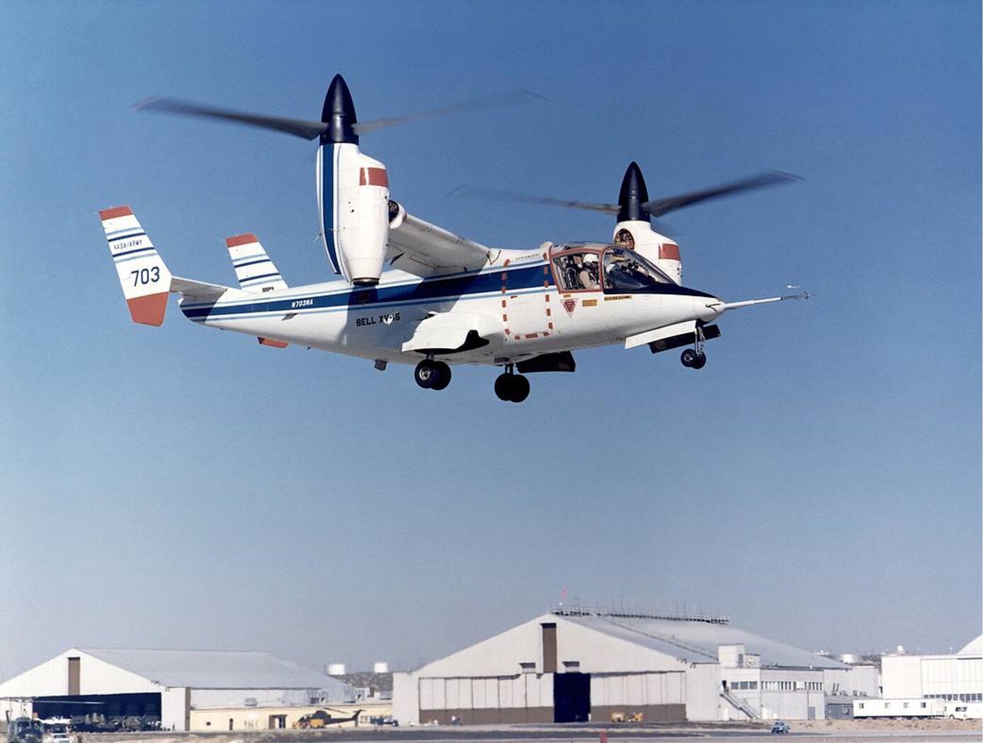
Improving VTOL Proprotor Stability
Proprotors on tiltrotor aircraft have complex aeroelastic properties, experiencing torsion, bending, and chord movement vibrational modes, in addition to whirl flutter dynamic instabilities. These dynamics can be stabilized by high-frequency swashplate adjustments to alter the incidence angle between the swashplate and the rotor shaft (cyclic control) and blade pitch (collective control). To make these high-speed adjustments while minimizing control inputs, generalized predictive control (GPC) algorithms predict future outputs based on previous system behavior. However, these algorithms are limited by the fact that tiltrotor systems can substantially change in orientation and airspeed during a normal flight regime, breaking system continuity for predictive modeling.
NASA’s Advanced GPC (AGPC) is a self-adaptive algorithm that overcomes these limitations by identifying system changes and adapting its predictive behavior as flight conditions change. If system vibration conditions deteriorate below a set threshold for a set time interval, the AGPC will incrementally update its model parameters to improve damping response. AGPC has shown significant performance enhancements over conventional GPC algorithms in comparative simulations based on an analytical model of NASA’s TiltRotor Aeroelastic Stability Testbed (TRAST). Research for Hardware-In-the-Loop testing and flight vehicle deployment is ongoing, and hover data show improved vibration reduction and stability performance using AGPC over other methods.
The example presented here is an application to tiltrotor aircraft for envelope expansion and vibration reduction. However, AGPC can be employed on many dynamic systems.

